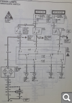
There is no pinout for the turn switch connector in the FSM, but there is this:
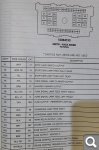
And C202 connector, I presume, has all the pins I'm going to need for my task:
With all this, I couldn't get the turn signal to blink, this is how bad with electricity I am. For example. A7 - turn signal lamp feed left front. Shouldn't left front lamp start to blink, if I connect A7 to A4, "turn signal lamp flasher output"? I mean - this is exactly what turn signal stalk is doing, when I move it, right? Well, apparently, it's not that simple - nothing blinks. And I can't see why ) Looking at the C202 connector description I even want to ask, what's the difference between "output" and "feed", but I won't, this is too embarrassing )
No it should not blink. This is what I was getting at saying that you have to check polarities, and clamp your circuit adds with diodes *or they wont work.* When you are checking polarities you will see that sometimes a lamp is made to blink by switching +12 to what appears to be the ground side of it, and other conveniences. The diagram shows what's wired to what but does not communicate the switching logic.
It's vexing.
So... it's not so much that you are bad with electricity, it's rather that aspects of the Riv's wiring are *very* old school (like, 1960's old school). I found that there was much I did not understand even just in maintaining the systems. For instance, when the taillight bulbs in my Riv get old enough, the turn signal makes phantom clicks. Nothing flashes, mind you, the stupid thing just clicks, for instance, when applying the brakes. First time it happened, I mentioned it on my next visit to the dealer's parts department and the department manager (Hal - he's still there) said, "oh just replace the light bulbs." He said he could not explain why they do that but it's not unique to the Riviera (for whatever reason). "Really, just replace them. It'll go away." I replaced them. The phantom clicking went away.
The adding of control electronics to the 60's floating-ground lighting system will bring you no end of interesting design and troubleshooting... and will frustrate modifications. Really, plan on using the Arduino to activate relays that you put in parallel to the existing switches, unless you actually test and tone out the various circuits and come up with a different approach (since the documentation you reeeeeeeally need isn't there).
AA Administrator
Name : Aaron Age : 47 Location : C-bus, Ohio Joined : 2007-01-13Post Count : 18452 Merit : 252
Subject: Re: Raspberry Pi microprocessor & Arduino microcontroller Sat Jul 04, 2020 9:30 am
albertj wrote:
For the Riv, a better solution for lane change feature might be a simple analog circuit that once it is pulsed holds itself high. I'd look (web search ) for an old Forrest Mims or Popular Electronics circuit for that one.
An Arduino controller can easily do this task. I made it difficult on myself by setting the constraint of needing to be plug & play in the flasher module. What seemed like a simple idea got complicated. Also, the flasher circuitry in my GTO is different, as it switches the negative side. Bet the Riv's wiring is more straightforward.
I did get it working on the bench, just never installed in the car.
Somewhere I have a stack of the Mims schematic books. Lots of fun in the '80s!
'70 Ninety-Eight Holiday Coupe 455cid • 116k miles ^^^ SOLD ^^^
albertj Master
Name : Location : Finger Lakes of New York State Joined : 2007-05-31Post Count : 8687 Merit : 181
Subject: Re: Raspberry Pi microprocessor & Arduino microcontroller Sun Jul 05, 2020 3:02 pm
AA wrote:
albertj wrote:
For the Riv, a better solution for lane change feature might be a simple analog circuit that once it is pulsed holds itself high. I'd look (web search ) for an old Forrest Mims or Popular Electronics circuit for that one.
An Arduino controller can easily do this task. I made it difficult on myself by setting the constraint of needing to be plug & play in the flasher module. What seemed like a simple idea got complicated. Also, the flasher circuitry in my GTO is different, as it switches the negative side. Bet the Riv's wiring is more straightforward.
I did get it working on the bench, just never installed in the car.
Somewhere I have a stack of the Mims schematic books. Lots of fun in the '80s!
I would *prefer* an Arduino especially if the interface could be (a) plug and play and (b) connected so that I could implement other features in software. For instance, to make the turn signals snap on and fade out when 'blinking.'
For doing just what the OP wants and no more, well the Riv's wiring is not much more straightforward than the GTO. For instance, the repeat function of the front side markers. The turn signal has 2 circuits, one for parking lights and one for flashing. The flashing circuit is bridged right and left separately to the side marker circuit (depending on the position of the turn signal switch) such that when the flashing circuit goes 'hi' it puts 12v on the *ground* side of the lit side marker, turning it off. They don't do that with the rear side markers because the flashing circuit also goes hi in the rear for brake lights. So the same strategy won't work, it would cause the rear side marker lights to go out each time you lit the brake lights for whatever reason.
On the other hand -- an analog circuit like that used to run the wipers when you blip the washer paddle on the turn signal stalk switch would connect right in to the turn signal control wiring, should splice into the harness (preferably just before the main connector from the steering wheel harness). You need one for the right and one for the left. All it would have to do is hold the blinker circuit high (as if it was the turn signal switch) for a few seconds once activated. A relay wired in parallel to each of the controlled lines from the turn signal switch would work. It would not inject power, it would just be an alternate way to temporrily close the respective turn signal circuit.
AA Administrator
Name : Aaron Age : 47 Location : C-bus, Ohio Joined : 2007-01-13Post Count : 18452 Merit : 252
Subject: Re: Raspberry Pi microprocessor & Arduino microcontroller Sun Jul 05, 2020 11:03 pm
Yeah, that makes sense. What we're talking about here is a bounce-less switch with delay. Fairly easy circuit to make with the 555 timer IC. You could adjust the delay to account for 2, 3, or 4 flashes per switch pulse.
I remember part of the dilemma with this was figuring out how to make the timer start the delay from the initial pulse on the signal switch. If instead the delay continued from the end of a long pulse (i.e. a normal latched signal turn), the a delay would be added on the end of every signal use. This wouldn't be the end of the world, but not winning style points, either.
Example scenarios for a 3 flash lane change (timing = 1 flash every 2 secs):
INPUT: ON >> OFF (1/2 sec) SIGNAL: 1st flash >> 2nd flash >> 3rd flash >> OFF
INPUT: ON >>> >>> >>> OFF (3 sec hold) SIGNAL: 1st flash >> 2nd flash >> 3rd flash >> OFF
INPUT: ON >>> >>> >>> >>> >>> >>> >>> >>> OFF (8 sec hold) SIGNAL: 1st flash >> 2nd flash >> 3rd flash >> 4th flash >> OFF
INPUT: ON >>> >>> >>> >>> >>> >>> >>> >>> OFF (8 sec latch) SIGNAL: 1st flash >> 2nd flash >> 3rd flash >> 4th flash >> OFF
'70 Ninety-Eight Holiday Coupe 455cid • 116k miles ^^^ SOLD ^^^
albertj Master
Name : Location : Finger Lakes of New York State Joined : 2007-05-31Post Count : 8687 Merit : 181
Subject: Re: Raspberry Pi microprocessor & Arduino microcontroller Mon Jul 06, 2020 12:41 am
OK. Probably the thing to do is use the Arduino-based module to replace the flasher - BUT - incorporate a relay in the module to actually do the flashing. Then, the side marker repeater (and the rest of the bits) will work as designed.
What you do is make it so the Arduino OR the turn signal switch will run the flasher relay circuit.
When you blip the switch, the relay is activated for 3-4 pulses no matter what. When you turn the switch 'on' and leave it on, then let the flashing circuit stay on. After 4 pulses the flashing from the Arduino quits whether the stalk switch is on or not.
AA Administrator
Name : Aaron Age : 47 Location : C-bus, Ohio Joined : 2007-01-13Post Count : 18452 Merit : 252
Subject: Re: Raspberry Pi microprocessor & Arduino microcontroller Mon Jul 06, 2020 6:53 am
That's close to the direction I remember going. There are prefab relay break-out boards for Arduino, required for handling any real current. You could use a solid state driver, but the relays are small, cheap and reliable.
'70 Ninety-Eight Holiday Coupe 455cid • 116k miles ^^^ SOLD ^^^
DeepFrozen Fanatic
Name : Dmitry Joined : 2016-08-28Post Count : 252 Merit : 11
Subject: Re: Raspberry Pi microprocessor & Arduino microcontroller Mon Jul 06, 2020 7:55 am
I already built and bench-tested everything. I have all kinds of relays, both electro-mechanical and solid state. I just don't know where to tap into the wiring )
albertj wrote:
A relay wired in parallel to each of the controlled lines from the turn signal switch would work. It would not inject power, it would just be an alternate way to temporarily close the respective turn signal circuit.
This, above, is exactly what I was planning to do. BUT. In the FSM there is no pin-out description for the turn signal stalk connector. I'd disconnect and examine this connector to find out what's actually happening when I move the stalk, but where is it? It must be somewhere deep inside the steering column, I couldn't find it.
AA Administrator
Name : Aaron Age : 47 Location : C-bus, Ohio Joined : 2007-01-13Post Count : 18452 Merit : 252
Subject: Re: Raspberry Pi microprocessor & Arduino microcontroller Mon Jul 06, 2020 11:02 am
Should be able to tap into the purple, light blue, and dark blue wires that lead to/from the stalk.
I don't know the design of the controller, but it would probably need to interface at these 3 points.
Probably don't need the connection at A4 for actuation, probably just need to know if A7 or A6 changed state. Connection at A4 is to drive the light. Then you just temporarily latch A6 or A7 to A4 respectively (relays) so the lights will blink. Need one SPST and one DPDT-center off relay. Let the relays turn off after the 'flash to pass' interval. If the turn signal switch is flashed to pass, then the controller-directed relay will run the respective circuit. Just clamp the DPDT to the left or right turn wire and clamp the SPST "ON" at the same time. The clamp current (from the controller driver circuit) turns itself off after the flash to pass interval. If the controller driver is ON while the switch is in position, it won't matter because the circuits are parallel and the turn signal will stay on until the switch is canceled by the cancel cam in the column--the controller having already run for its interval and turned itself off.
You might be able to eliminate the SPST relay if it does not affect controller actuation or timing.
AA Administrator
Name : Aaron Age : 47 Location : C-bus, Ohio Joined : 2007-01-13Post Count : 18452 Merit : 252
I think we're saying the same thing. Tapping A4 provides the controller with +12 from the flasher, so it can decide to bypass the stalk (no matter its state) and provide signal to whichever lamp it chooses. One thing I'm not sure: can the connections at A6 and A7 work as both sensing (tells controller the stalk was selected L/R), and also as sending (relay to drive flasher lamps). I think they can.
Example for operation: If you momentarily switch stalk to L signal, the controller senses +12v input on A7 and keeps A7 high for the programmed length of time (~3 flashes), regardless the position of the stalk. The controller simply reroutes output from A4 to A7 for 3 flashes, then goes low (done, ready for next input).
The timer starts from each new detection, so if the stalk were switched to L signal, then quickly to R signal, the controller would abandon the high state to A7, then make A6 high and complete the cycle.
My first guess with A6 and A7 is to clamp them with diodes that lead separately to the sensing and sending parts of the Arduino module and make the Arduino ignore the sensing input if it is already sending the output high. That said I would double check if this circuit as it is, is it switching hots or grounds. Which is which impacts your control strategy. Check it with a meter he he. The diagram does not really say because it is a functional diagram not a wiring diagram per se and did you notice the grounds are not really shown??? (hint - they are in the control modules and the off-page references)
AA Administrator
Name : Aaron Age : 47 Location : C-bus, Ohio Joined : 2007-01-13Post Count : 18452 Merit : 252
I already built and bench-tested everything. I have all kinds of relays, both electro-mechanical and solid state. I just don't know where to tap into the wiring )
albertj wrote:
A relay wired in parallel to each of the controlled lines from the turn signal switch would work. It would not inject power, it would just be an alternate way to temporarily close the respective turn signal circuit.
This, above, is exactly what I was planning to do. BUT. In the FSM there is no pin-out description for the turn signal stalk connector. I'd disconnect and examine this connector to find out what's actually happening when I move the stalk, but where is it? It must be somewhere deep inside the steering column, I couldn't find it.
Pull the sound panel under the drivers side dash and look up, you can't miss the fat harness coming out from behind the clamshell at the top of the steering column.
albertj Master
Name : Location : Finger Lakes of New York State Joined : 2007-05-31Post Count : 8687 Merit : 181
Some good ideas. I was thinking diodes or some opticoupler isolation.
Yeah, I can follow it with the grounds missing. My GTO is the opposite. All they show are the grounds - must be a "land down under" thing.
Aaaaargh! it's not that complex - it's just that current can move in one direction or another on the actual lamp circuit so they used a relay to just close and open it. Really... just diode clamp your control lines and use a relay for the lamp circuit.
DeepFrozen Fanatic
Name : Dmitry Joined : 2016-08-28Post Count : 252 Merit : 11
Subject: Re: Raspberry Pi microprocessor & Arduino microcontroller Thu Aug 27, 2020 12:15 pm
First test of my Arduino HUD. Looks promising If anything - the speed is in km/h.
I read data from the OBD2 through ELM327 and Bluetooth. Turned out it is easier than to count impulses from the PCM.
AA likes this post
Sponsored content
Subject: Re: Raspberry Pi microprocessor & Arduino microcontroller
Raspberry Pi microprocessor & Arduino microcontroller