Name : Andrew Age : 40 Location : Ontario, Canada Joined : 2008-01-14Post Count : 1949 Merit : 123
Subject: *one* of my back-burner projects Tue Apr 13, 2010 1:32 pm
So I have a bit of a back burner project going on. It was supposed to be taking a back seat, but there has actually been quite a bunch of work done on it. I have no idea when this will be done, if all goes well, maybe next year sometime. Please excuse the verbal diarrhea, this is not the most logically laid out overview of my plans.
At the very least, many of you should find the pictures interesting, as it outlines the porting process of a supercharger.(Keep in mind that the below images shows a VERY aggressive port job that has been specifically calculated for the inlet size. I've ported quite a number of blowers in the milling machine and I've done the math here, don't replicate it for a blower with a different inlet.)
There won't be much technical details in here, since I have that all stored on the other computer, and since much of it will be done as I go. I find my best projects with the most impressive results are those where I just continuously do research on it, and just make it up as I go along.
so, here it is. The beginning work for the first ever 3.8 series one m62 to m90 swap.
The start of this idea came when I found a deal on the m90 supercharger from a 94-95 Ford Supercoupe. I seem to obsessively buy superchargers. I fill my house with them, and have ported many of them in the milling machine. Currently there is an m62, an m90, and a gen V sitting in the kitchen. It must be some kind of sickness.
anyway, some info on the m90 from the Ford Supercoupe. They are upside down orientation, and pipe through a front mount air-to-air inter cooler. years <=93 had no coating on the rotors (like the same years m62) and the 94-95 had epoxy coated rotors(like the 94-95 m62). The 94-95 casing are quite rare and can be spotted by the square inlet hold instead of the oval one of previous years. The 94-95 also came stock with an 8rib, 3.3" pulley. The smaller pulley was dues to pressure drop through the inter-cooler, and the less efficient blower(compared to our 96-97/98-99 m90s). FYI: the SC rotor coating on our m90 is slightly different on the rotors between 96/97 and the 98+ ones. Then the gen V came along and changed it up again.
Here's some good info on the m90 from the Ford Supercoupe: http://www.sccoa.com/articles/blowerbuild.php
What I have found really neat is the numbers that the Supercoupe guys have pulled out of this blower considering that the best they had was the older epoxy coating like what we have on the m62. While pouring through their web forums for hours I found that the reason was that for years, they haven't been afraid to "just try it." I've noticed on many car forums now-a-days that good ideas get "Discussed to death" and never see testing. Many an idea just needs to be tried. And I feel that much of the success that the ford super coupe guys have had was due to just giving it a try and letting 1/4 times and dyno numbers speak for the results. Many of the work they have done to their m90 have been contrary to what Eaton suggests, but has worked anyway. I tell you, few other groups of car enthusiasts have cut up, hacked, and welded their stock blower so much.
A very modded ford super coupe blower is usually known for its big smile! :
Anyway, enough of that. I'll let the pictures do the talking. Here's what I've been up to:
Above is my ford m90 and below is an older junker m62. Notice how the length of the ford m90 is VERY workable for adapting. I've never seen a more compact m90.
A few more pics:
(Upside down orientation)
The setup I was considering is to use the m90 in an upside down orientation. A custom throttle adapter and boost dump valve would be made. Due to the large mouth, I'm thinking of twin throttle bodies. I admit, some of it is "look cool factor", but there is method too. The stock series one l67 has a 69mm throttle plate. Just shy of that of a northstar. The inlet of this m90 will be opened to around a northstar and a half. So any easy breathing will be a help. Already I'm going to have so get creative with tuning(I could do a whole other thread about 95 series one tuning research) and there is custom work anyway, so twin TBs are not really much extra work. Also the aussies have had good luck with them on their 3800's. Just leave the fine details to me...
The upside-down blower also has another benefit in that it will only touch the engine on three posts. A great way to prevent heat-soak.
At first I was thinking of a custom water-to-air IC, similar to these:
With long intake runners wrapping around. But now I'm exploring how I'd set it up for air-to-air inter-cooling. For the LIM I will probably use an l27 LIM from a NA series one, since I have one on another car. My guess is I'll make a custom plate to tie everything together.
so then, on to the work that's been done. Lets have a look at the porting progress:
I've got to say, this is the easiest supercharger ever to put into the milling machine: (I had to use the old milling machine, the new one had a job setup in it )
I usually indicate out the original angle and match it to the Y-axis:
Then I run a cutter down the edge just brushing. That becomes my indicated edge. I set the digital readout to 0 here.
Its worth mentioning that although this blower is older, its better made than even the gen V. The casting is VERY smooth, and spare surfaces are epoxy coated.(the yellow you see across the output plate in the above 2 pics) Its like Ford paid Eaton more for making them.
I usually hog out the bolt protrusions a little at a time to match the indicated edge:
For this porting job, I'm relying on past experience, mixed with the standards that are maintained by the Ford Supercoupe guys. The result is a sorta hybrid, that we will see how it preforms.
I'm actually removing .25" off each side 0_0 (For normal blower porting keep it to < 1/8" , more like 1/16" !! )
Here we see where I've roughly indicated how much the triangle will move when the corners merge on center with the material removed:
This is a combination of "actual" machining, and me eyeballing things.
I then indicate the opposite side after flipping the part:
Same deal with the bolt protrusions:
Here we can see how sweet the angle of the rotors is with the angle of the outlet:
Cleaning up the back edge:
Finished outlet shape:
The outlet will still need some TLC with the Dremel to round things up where needed, all done for the angles of airflow at WOT.
Now onto the inlet: Here's the big happy guy:
All mounted in the mill:
Finished inlet:
Detail of things to be cleaned up:
I need to do a bunch of smoothing on the inlet, as well as working out the throttle body attachment plate. Fortunately the blower is really short, and I have lots of room to play around. I'll probably end up making something with bits of aluminum and TIG something up. What it will need is a smooth run from each TB and a smooth transition to the square hole. I'm odd that way, but I really love making the little details, which this project will be rich with.
Anyway, thanks for reading, this is just a little glimpse into what I'm working out. I really don't even know when I'll have another stab at this project, since I have a list 40 major items long of things that I need to get done on the 95 before it goes back on the road in a month.
A few random Fun links for reading from my collection: http://www.sccoa.com/forums/showthread.php?t=64841&highlight=snout+bearing http://www.rollingperformance.com/snoutrebuild.htm http://www.sccoa.com/forums/showthread.php?t=49012&highlight=SUPERCHARGER+SNOUT+REBUILDING+INSTRUCTIONS http://forums.tccoa.com/showthread.php?t=123198 http://forums.hybridz.org/showthread.php?t=115326 http://www.harrop.com.au/performance_products.html http://www.motorgeek.com/phpBB2/viewtopic.php?t=29949 http://www.bellintercoolers.com/pages/lacore.html http://www.dubsinthebuff.com/forum/site-sponsors/18210-well-we-now-have-sub-20k-supercharger-solution-v8s4s-2.html http://www.thinkythings.org/3800/3800.html http://www.honda-tech.com/showthread.php?t=1997913&page=48 http://www.galantvr4.org/ubbthreads/showflat.php?Board=UBB11&Number=554229&page=0&fpart=1 http://forums.bimmerforums.com/forum/showthread.php?t=1258722 http://www.enginebuildermag.com/Article/3107/intake_manifolds_from_mild_to_wild.aspx http://forums.vwvortex.com/zerothread?id=1094961
_________________
deekster_caddy Master
Name : Derek Age : 52 Location : Reading, MA Joined : 2007-01-31Post Count : 7717 Merit : 109
Subject: Re: *one* of my back-burner projects Tue Apr 13, 2010 2:03 pm
awesome! nice work! There are so many times I wish I had access to the machinery like I used to.
I'm very curious to see what your throttle body ends up looking like.
turtleman Expert
Name : Codith Age : 37 Location : Villa Park, IL Joined : 2007-02-08Post Count : 3671 Merit : 140
Subject: Re: *one* of my back-burner projects Tue Apr 13, 2010 2:09 pm
Interesting indeed! Would you say there's no point in doing tapers and angle cuts on the outlet edges like some do? I alwasy thought that looks really good on a machine but from your research, is there any benefit?
Karma Aficionado
Name : Andrew Age : 40 Location : Ontario, Canada Joined : 2008-01-14Post Count : 1949 Merit : 123
Subject: Re: *one* of my back-burner projects Tue Apr 13, 2010 2:33 pm
turtleman wrote:
Interesting indeed! Would you say there's no point in doing tapers and angle cuts on the outlet edges like some do? I alwasy thought that looks really good on a machine but from your research, is there any benefit?
I wasn't sure if you meant the shape of the outlet, or the contour of the edge for the outlet. So I answered both:
For the shape, I feel that there is some benefit to backing the triangle off from the main triangle shape slightly.
This is similar to the new Eaton TVS, though the shape is really meant for the new twist shape in the TVS rotors. Due to the twist in our rotors, I think it can help pick up some airflow when we are over-spinning the blower. In our application think of it a slight pre-loading to help direction in the airstream. Edit: Above you can see how the trapped air would begin its exit a little earlier before the rest of the rotor has hit the edge. It has to do with the helix twist in the rotors against the 2-dimensions of the triangle.
I would not use this shape on a blower that i did not intent to spin ridiculously fast. This is just my personal feelings though.
For the contour of the edge, smoother is always better. The sharp edges in my first post need work, as they are just currently the cutout of the shape.
When we look at the air-path as it leaves the blower it should become clear on how the edge profile should be to maintain best flow and prevent heat-up: We have the air doing a nice run around the inside radius of the casing, and the last thing we really want is having it striking across a sharp edge.
_________________
turtleman Expert
Name : Codith Age : 37 Location : Villa Park, IL Joined : 2007-02-08Post Count : 3671 Merit : 140
Subject: Re: *one* of my back-burner projects Tue Apr 13, 2010 4:19 pm
I mean like that. The edges are angle cut instead of straight cut. I don't think the angle cut is even all the way to the inside of the case but it doesn't look like it would be a bad thing.
Karma Aficionado
Name : Andrew Age : 40 Location : Ontario, Canada Joined : 2008-01-14Post Count : 1949 Merit : 123
Subject: Re: *one* of my back-burner projects Tue Apr 13, 2010 4:25 pm
I am of the opinion that the inside edge benefits most from rounding. Though any rounding in the right places IMO is a good thing. Smooth and gentle curves. Like a woman.
_________________
AA Administrator
Name : Aaron Age : 47 Location : C-bus, Ohio Joined : 2007-01-13Post Count : 18452 Merit : 252
Subject: Re: *one* of my back-burner projects Tue Apr 13, 2010 4:31 pm
The Triple Edge machining around the silencing ports is what I would call 'beveled' or 'chamfered'. Andrew is right that rounding is the best, but chamfering is easier to do, less expensive, and works almost as well.
'70 Ninety-Eight Holiday Coupe 455cid • 116k miles ^^^ SOLD ^^^
Karma Aficionado
Name : Andrew Age : 40 Location : Ontario, Canada Joined : 2008-01-14Post Count : 1949 Merit : 123
Subject: Re: *one* of my back-burner projects Tue Apr 13, 2010 5:08 pm
It gets interesting too, in that the actual material changes thickness between the wide part of triangle and the narrow part. Has to do with the shape of the rotors and how they contact with the casting floor. When you run a machined bevel, even if perfect, it looks "off" from the changing thickness. Again though one part that I think gets missed when porting outlets, is the inside or back edge of the triangle. From the exit angle of the air, it "shears" across it and can build heat if not rounded or smoothed. Remember, the air exits at angles in pulses against each other. Not straight down into the lim.
_________________
Rickw Guru
Name : Rick Location : Lancaster, MA Joined : 2008-09-13Post Count : 6282 Merit : 119
Subject: Re: *one* of my back-burner projects Tue Apr 13, 2010 5:41 pm
Karma, I have a couple of questions regarding the cutout shape of the outlet or Christmas tree. Your finished shape obviously increases the width of the bottom of the triangle, Correct. When do you know that you have milled the correct amount for that width measurement.? In other words, how do I determine the width to mill my GenV without over or under doing it.?
Is it solely based on the angle of the Rotors.?
And also at the top of the tree or triangle you have milled an additional amount, about the diameter of your cutting bit or more, so that it alters the perfect triangle shape at the top of the tree. What benefit does that additional cutting have and how are you determining how much to cut at that end of the outlet.? Is it again based on the rotors and if so how?
I have milling machines available for my use occasionally and have a stock Gen V that i would like to mill, blend the outlet shape and polish.
So I have many questions I guess with out having seen a GEN V properly milled, ported and polished.
Back to the one in the picture above, I know you are showing this outlet opening after the first stage, just milling leaving a knife edge at this point. You have alluded to the finished product of the triangle will be to round the edges inside and out, is this correct. So the finished shape of the edge cross-section will be a circular one and not an abrupt straight edge.?
Regarding the GEN V there is the rectangular opening for the outlet port, as you look closer toward the intake or by-pass port there is a aluminum wall separating the triangular outlet from a cavity in the housing. Should this wall be removed and if so why. I think I have seen pic's of a GEN V with this part of the casting removed but I cannot see any benefit to it. I'm sorry I don't have pictures to help better explain, if you do not understand. If you have some pic's of a properly ported GEN V then that would be greatly appreciated as well. Thanks, Rick
Last edited by Rickw on Tue Apr 13, 2010 6:15 pm; edited 1 time in total
IBx1 Expert
Name : ILAN Age : 33 Location : College Station, TX Joined : 2007-12-30Post Count : 4304 Merit : 69
Subject: Re: *one* of my back-burner projects Tue Apr 13, 2010 5:43 pm
As soon as you mentioned it in the beginning, I couldn't help but laugh at the last few pictures with the big happy face!
Karma Aficionado
Name : Andrew Age : 40 Location : Ontario, Canada Joined : 2008-01-14Post Count : 1949 Merit : 123
Subject: Re: *one* of my back-burner projects Tue Apr 13, 2010 6:46 pm
Rickw wrote:
Karma, I have a couple of questions regarding the cutout shape of the outlet or Christmas tree. Your finished shape obviously increases the width of the bottom of the triangle, Correct. When do you know that you have milled the correct amount for that width measurement.?
Is it solely based on the angle of the Rotors.?
The porting in this thread is based on the results of the Ford Supercoupe crowd. The aggressive porting shown is a mix between the accepted .25" wider from the Ford guys, my own experience porting, and my calculations. If it is effective, I'll find out when its running. ( That was my little disclaimer)
For generic porting, anytime I port a blower, I always keep the rotor angle; so I suppose you could say that everything is based on that angle. The width will be determined by how much material you take off at the sides. What I do is work out how much overall area that I want to open by. I try and keep the ratio of inlet area vs. outlet area. In this case, the inlet was getting opened up a LARGE amount, so figuring the ratios and adding the additional amount that is customary to open the outlet when spinning the blower faster: it came out to what can be seen in the pics. Once I've worked out how much wider I want it, the edge is zero'ed off in the machine and the cuts are run until they intersect.
So, in short: I draw a picture with the dimensions of the current triangle(i ignore the bolt protrusions). Then draw another triangle simulating the material removed. If drawn to scale you can calculate the extra area. Once it is what is wanted, the material is taken off the sides matching the angle of the rotors.
Rickw wrote:
And also at the top of the tree or triangle you have milled an additional amount, about the diameter of your cutting bit or more, so that it alters the perfect triangle shape at the top of the tree. What benefit does that additional cutting have and how are you determining how much to cut at that end of the outlet.? Is it again based on the rotors and if so how?
To be honest, alot of that is guessing. I'll see how it works out. I believe BillBoost once ported a blower similarly that worked well on someone's car.
My rationale is similar to a knife blade that changes its angle, like a kukri or machette. Since moving air reacts much like water, I feel that it helps the flow's "angle-of-attack". Picture a straight edge with water flowing over it. It works well in a line, but when you throw a swirl of water at it you end up with chaotic flow. Our blowers also are pushing the air in a swirl that needs to be pictured in three dimensions. It curves around the sides of the housing, and it spirals through the helix of the rotors.
As you can see in the above picture, one part of the rotor edge breaks first, allowing some of the air through the "extra machined bit". I feel that this helps shift the direction of momentum from firing all your air out on an angle towards the blower snout. If you take a stock blower and give it a good spin, you can feel that the air not only comes out in angles across the exit, it also biases towards the wide section of the triangle(of course). I find that the little taken out shifts the flow to a smoother downward direction. We need the triangle shape for the helix shape of the rotors to work, but the slight changes can modify how the air-stream exits the blower. I think this is the reason that the "mp" gen Eatons from magnuson have the shape that they do. http://www.magnusonproducts.com/images/mp62draw.jpg (It should also be noted the rim lip around the triangle outlet on the MP blowers. Think of it as similar to the rounded top lip velocity stacks on old big block NA builds, I believe the rationale is the same. ) So, I'm trying a slight lean to that kind of shape.
Rickw wrote:
I have milling machines available for my use occasionally and have a stock Gen V that i would like to mill, blend the outlet shape and polish.
So I have many questions I guess with out having seen a GEN V properly milled, ported and polished.
Back to the one in the picture above, I know you are showing this outlet opening after the first stage, just milling. You have alluded to the finished product of the triangle will be to round the edges inside and out, is this correct. So the finished shape of the edge cross-section will be a circular one and not an abrupt straight edge.?
Yes, the above images are not finished. A curved circular cross-section is needed so the air is not shearing across a sharp surface. The air exits in alternating pulses from each rotor, and cross in the 3d space above the triangle with a velocity bias towards the wide end of the triangle.
Rickw wrote:
Regarding the GEN V there is the rectangular opening for the outlet port, as you look closer toward the intake or by-pass port there is a aluminum wall separating the triangular outlet from a cavity in the housing. Should this wall be removed and if so why. I think I have seen pic's of a GEN V with this part of the casting removed but I cannot see any benefit to it. I'm sorry I don't have pictures to help better explain, if you do not understand.
If you have some pic's of a properly ported GEN V then that would be greatly appreciated as well. Rick
The wall is often removed to help air better disperse across an inter-cooler core. If you haven't an inter-cooler, there is no point in removing the wall. Cutting it with no inter-cooler will also leave a void across the top of your LIM which will cause slight turbulence. Whether the turbulence will make a difference can only really be measured with fluid flow testing or 3d simulation modeling. I suspect in the whole scheme of things it makes little difference though.
I haven't put the Gen V to the knife yet, but I can say that there is little I would change. The outlet shape and how the rotors are secured actually pulls the rotors back in the triangle slightly(towards the small end ), which I've found shifts the air-stream downwards already. Even the bolts that normally protrude on a gen3 m90 are already gone (I've got it in my lap right now). If you look closely at the small end of the triangle, you will see that the curve of the rotors has a little bit of metal poking towards them. The bit is not there on previous gens, which causes a little pocket of dead air space. That little extra bit of porting I did above removes the dead air space on older gens, but by having that filler and removing the pocket entirely I don't think pulling the porting back is needed on the gen 5 design. I think I would take off a conservative 1/16 around the triangle, round out the profile and call it a day. Obviously the inlet would get smoothed out too.
_________________
Mr.Riviera Expert
Name : Matthew Age : 38 Location : Florida Joined : 2007-01-17Post Count : 4394 Merit : 101
Subject: Re: *one* of my back-burner projects Tue Apr 13, 2010 7:43 pm
You're my hero Karma That is some serious fab work you are undertaking. So what are you doing with the gen V in the kitchen??
_________________ 1996 with 254k miles, L32 4" FWI -> ported N* -> Ported Gen V w/3.0" Pulley, Stage 3 Phenolic I/C, ZZP FMHE, 1.84 RR, Headers and 3" pipe to mufflers, F-body brakes, and lowered on Eibachs. -RIP AMG C400 White on black. Stage 2 w/E30 - 11.9@117 -daily
Karma Aficionado
Name : Andrew Age : 40 Location : Ontario, Canada Joined : 2008-01-14Post Count : 1949 Merit : 123
Subject: Re: *one* of my back-burner projects Tue Apr 13, 2010 9:42 pm
Its for the wife. .. I want her rotors from her gen3... to eventually swap into the ford supercoupe supercharger... great thing is the better rotors swap right over...
_________________
Rickw Guru
Name : Rick Location : Lancaster, MA Joined : 2008-09-13Post Count : 6282 Merit : 119
Subject: Re: *one* of my back-burner projects Tue Apr 13, 2010 9:49 pm
Karma, Thanks for the breakdown and the insight into doing a GEN V. I'll remove a parallel piece, 1/16", on each side of the triangle and lengthen it some at the bottom. Then just round over the sharp edge. That should be good for the outlet. Then just port the inlet to 77mm for the N* TB and polish as much as possible. Maybe I can get them to help me set it up on the flow bench if they are not to busy. The 2 Flow Benches are / were set up for Harley heads. Will require some fixture work, etc. I don't know if I'll get to use one of the flow benches, but I do know i can use one of the milling machines and porting and polishing cabinet. I also want to do some smoothing of the L32 LIM runners while I'm there. Would be nice to port match, but would have to have the heads off to do it right. Rick
Rickw Guru
Name : Rick Location : Lancaster, MA Joined : 2008-09-13Post Count : 6282 Merit : 119
Subject: Re: *one* of my back-burner projects Tue Apr 13, 2010 9:53 pm
Karma wrote:
Its for the wife. .. I want her rotors from her gen3... to eventually swap into the ford supercoupe supercharger... great thing is the better rotors swap right over...
How can you effectively measure the ID of the bores and then measure the clearance of the rotor to bore in order to be safe. And what should the safe gap be.? The last you'd want is to have the rotors stretch while hot and score the bores. Which grows more under normal operation the case or the rotors.?
Karma Aficionado
Name : Andrew Age : 40 Location : Ontario, Canada Joined : 2008-01-14Post Count : 1949 Merit : 123
Subject: Re: *one* of my back-burner projects Tue Apr 13, 2010 10:31 pm
Rickw wrote:
Karma wrote:
Its for the wife. .. I want her rotors from her gen3... to eventually swap into the ford supercoupe supercharger... great thing is the better rotors swap right over...
How can you effectively measure the ID of the bores and then measure the clearance of the rotor to bore in order to be safe. And what should the safe gap be.? The last you'd want is to have the rotors stretch while hot and score the bores. Which grows more under normal operation the case or the rotors.?
Often in high mileage superchargers you will find the bores scored anyway. Especially if they are over spun. The needle bearing start to give way and the rotors flutter. This effect is accented by smaller pulleys which cause the airflow to actually start to move the rotors in the pack length-ways, making the problem worse.
The rotors grow more than the case, this is in the design of rotors that are post epoxy coating. (so > 95 years). The epoxy coating is just to tighten tolerances and wears in to the bore in the breaking in period at Eaton just after assembly. The 96-97 rotors saw improvements that is a strange mix of things and expands slightly when heated to fill the bore. 98+ saw the introduction of an improved teflon and magic stuff to the rotor coating as well as better adhesion to the rotors themselves. The gen 5 rotors are a fun strange coating that is designed to "wear into" itself and keep expanding for the ultimate long life and efficiency. You can hear the coating on the rotors expand by listening to the difference when starting the car up in the winter vs. when it warms up. At first you can hear the cold rotors in that "vacuum cleaner" sound at first start up. Once they warm up, the coating expands, they center better, and you don't hear the same grinding noise.
.. and I know the rotors will fit in my bore for the ford blower because the SC crowd would often change to the more efficient teflon coated rotors from *our* blowers. They would see the equivalent results of a .2"-.3" pulley drop just by swapping rotors, with the benefit of no extra HP required to turn and same heat output.
.. good grief... I'm realizing just how much info I've picked up over the past few years in my fanatic reading of supercharger info by answering these questions!
_________________
Rickw Guru
Name : Rick Location : Lancaster, MA Joined : 2008-09-13Post Count : 6282 Merit : 119
Subject: Re: *one* of my back-burner projects Tue Apr 13, 2010 11:59 pm
Thanks Karma, you saved me a bunch of time trying to find these answers and I knew nothing about the Ford Blower crowd. So I was at a disadvantage to start with.
With my current Gen 3 and 108,000 miles I started hearing the noise you speak of about 4 or 5 months ago during the first minute or two of running time and then it goes away. I assumed it was the tolerance between rotor and housing and the noise dissipates when the rotors grow. But I wasn't quite sure because it doesn't take that long for the noise to go away. So it is a bit baffling, because I didn't think the rotors would actually grow that quickly. Once I put the GenV on I'll be able to do a tear down on the Gen 3 and have a good look.
Another question you may have knowledge on is the use of water/meth (windshield washer fluid) on these blowers. I've heard conflicting reports and no pictures to back it up. But there is talk of the water meth removing the coating from the rotors. After reading what you said about the different coatings depending on years and generation of supercharger I'm wondering if you know of the affect the fluid has on the various coatings used. I'm talking about using one of the systems that is controlled by MAF frequency and sprayed in an atomized mist. Not just poured into the intake in front of the TB. In your research have you come across any info regarding the use of water meth. It is something I would like to try to cool the intake temps but not at the detriment of the rotors.
Karma Aficionado
Name : Andrew Age : 40 Location : Ontario, Canada Joined : 2008-01-14Post Count : 1949 Merit : 123
Subject: Re: *one* of my back-burner projects Thu Oct 21, 2010 9:54 am
Ah, I didn't notice the question above way back. Sorry Rick...
For meth and rotor wear, what I've learned is this: -Uncoated is obviously fine -anything from 93-95 is epoxy(and stuff) coated and WILL come off with meth. -96 was a transition year, and while it shares similar coating to the 97+ the prep work was not done as well and sometimes the rotors would peel(even without meth) -97+ the coating was very slightly modified and the rotor prep was much better done. Many have sprayed meth with success with these rotors. -Gen V rotors are supposed to have no problems with meth, but most people still haven't due to the cost of the blower and the increasing difficulty in finding them.
And to my original reason for posting in this thread: I've been thinking lately about how I'm going to do the custom m90 swap, and I'm leaning more towards a complete re-make of the LIM so the blower is recessed more as well as maybe going A2A inter-cooling. But thats besides the point; I was looking at manifold designs and came across this: http://v8tvshow.com/forum/index.php/topic,2016.msg3488.html
Gave me a "fabrication-gasam". I could die happy if I could make welds like that.
_________________
robotennis61 Guru
Name : robotennis Age : 63 Location : las vegas Joined : 2007-12-17Post Count : 5562 Merit : 143
Subject: Re: *one* of my back-burner projects Thu Oct 21, 2010 10:05 am
whoa! thats incredible work!
Abaddon Expert
Name : Scott Location : Macomb, Michigan Joined : 2010-02-24Post Count : 4316 Merit : 185
Subject: Re: *one* of my back-burner projects Thu Oct 21, 2010 10:11 am
Whoa is right. I don't even wanna know the price tag
Karma, I know you have a lot of work into your '95, but have you considered just doing an L67 engine/trans swap? It'd probably be cheaper and less time than fabbin' up a manifold like that!
Karma Aficionado
Name : Andrew Age : 40 Location : Ontario, Canada Joined : 2008-01-14Post Count : 1949 Merit : 123
Subject: Re: *one* of my back-burner projects Thu Oct 21, 2010 12:05 pm
Abaddon wrote:
Karma, I know you have a lot of work into your '95, but have you considered just doing an L67 engine/trans swap? It'd probably be cheaper and less time than fabbin' up a manifold like that!
(but I have an l67... Technically the 95sc IS an l67 )
Ha-ha, well I already have a series two drain on my wallet in the form of the wife's 98 riv. The stuff I'm doing on my series one is for the challenge and the fun. For me, the fabbing is cheap cause its just my own time, and I just plain enjoy designing/engineering/machining. I guess it becomes a passion when you grow up with a prototyping machine shop at your disposal and have been making things in it since age 8. Also, I have other reasons for working with the series one, one of which is the taller deck height which goes a long way to making a more reliable stroker. I series two *can* be stroked, but a series one would be much more stout for crazy things.
_________________
Rickw Guru
Name : Rick Location : Lancaster, MA Joined : 2008-09-13Post Count : 6282 Merit : 119
Subject: Re: *one* of my back-burner projects Thu Oct 21, 2010 12:37 pm
Karma wrote:
Ah, I didn't notice the question above way back. Sorry Rick...
For meth and rotor wear, what I've learned is this: -Uncoated is obviously fine -anything from 93-95 is epoxy(and stuff) coated and WILL come off with meth. -96 was a transition year, and while it shares similar coating to the 97+ the prep work was not done as well and sometimes the rotors would peel(even without meth) -97+ the coating was very slightly modified and the rotor prep was much better done. Many have sprayed meth with success with these rotors. -Gen V rotors are supposed to have no problems with meth, but most people still haven't due to the cost of the blower and the increasing difficulty in finding them.
I sold my Gen V and plan on staying with the Gen 3 for now. So I might get and install a water meth system yet. I want to put a temp sensor in the LIM and be able to read it on the Aeroforce gage and measure the difference from non- W/M and with W/M. Just curious. And if by chance the coating starts to get hammered by the spray then I'll just get another S/C or disassemble this one, rebuild it and remove the coating completely. I don't know for sure, I'm just thinking out loud for know.
Thanks for the reply and the knowledge you gained from researching the coatings.
Rick
Abaddon Expert
Name : Scott Location : Macomb, Michigan Joined : 2010-02-24Post Count : 4316 Merit : 185
Subject: Re: *one* of my back-burner projects Thu Oct 21, 2010 1:44 pm
Karma wrote:
Ha-ha, well I already have a series two drain on my wallet in the form of the wife's 98 riv. The stuff I'm doing on my series one is for the challenge and the fun. For me, the fabbing is cheap cause its just my own time, and I just plain enjoy designing/engineering/machining. I guess it becomes a passion when you grow up with a prototyping machine shop at your disposal and have been making things in it since age 8. Also, I have other reasons for working with the series one, one of which is the taller deck height which goes a long way to making a more reliable stroker. I series two *can* be stroked, but a series one would be much more stout for crazy things.
I envy you sir
You're right, it's more fun to fab stuff up. That way what you do have is 1 of a kind
Karma Aficionado
Name : Andrew Age : 40 Location : Ontario, Canada Joined : 2008-01-14Post Count : 1949 Merit : 123
Subject: Re: *one* of my back-burner projects Fri Feb 11, 2011 11:59 am
So I've been doing lots of thinking about this project lately. I've been flip-flopping between going for an air-to-air inter-cooler, or water-to-air, and I think just due to intake ducting ease, I'll go W2A. This gives me more flexibility with the intake manifold design to get the correct shape and length of runners to fit under the hood with the new supercharger.
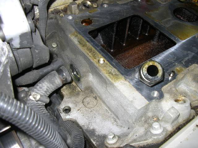
Currently I'm leaning towards milling out a LIM so I can use the stock coolant passages. (instead of custom making an entire LIM) The plan would be to TIG some flanges onto the walls of a series one "walled" LIM to direct the runners up from the heads. (they would be milled back as far as I can to make room) . Or maybe I'll just mill the whole thing out and re-do the injector ports. Then I can get a better spray angle at the back of the valve.
You can see the walls in the LIM on the sides of the intake runners in this pic:
The SC would actually sit at the bottom of the original LIM plenum to lower its height since the Ford SC "blows up". The runners would wrap up around the SC, and into the inter-cooler cores. I'm planning on one core for each bank of 3 runners similar to one of the pics on the first page of this thread. So instead of the blower firing its charge straight into one end of the IC core like on most series two setups, it will hit two 1/4 moon shapes and direct to the sides, through the IC core, and straight into the runners. Its hard to explain, but whenever I finish my 3d models I'll put up pics. This should remove most of the flow turbulence that occurs in traditional setups where the air must exit the output of the SC, straighten out for the IC core, and then make a 90 degree turn right on the fin edge to head in the direction of the runners.
I've also been pouring over websites and forums that discuss intake plenum design, resonance tuning, runner length and RPM band tuning, air dynamics flow, etc. Lots of interesting stuff. Running the calculations for runner length, and keeping the runner area of 1.71 square inches(stock head runner size for me), I tried all the different schools of thought and different formulas and found some interesting things. For my engine, averaging the results of the different formulas I end up with runner lengths that run in the ball park of 14-15" or 19-22" from the back of the valve to plenum. (granted most of this goes out the window with FI but the main goal for me is to maintain velocity and inertia between valve pulses to overcome the disadvantage of having smaller valves that you s2 guys) *If* i can fit it, I would prefer to work out 22" runners, as it gives me the BEST pulse strength across RPM range in the 2nd, 3rd, and 4th harmonic.
An easy online calculator gave me this for 22 inches: Input length is 22 inches For 2nd harmonic, RPM range is from 5340 to 6480 with a pulse strength of 10 percent For 3rd harmonic, RPM range is from 4012 to 4585 with a pulse strength of 7 percent For 4th harmonic, RPM range is from 3128 to 3498 with a pulse strength of 4 percent
And it gets further supported by other calculations that takes into account engine displacement, cam timing, valve opening events, runner area, and targeted peak toque RPM.
When I put all the methods together I found that the accepted rule of thumb of having "total runner area = the amount of air one cylinder displaces" to be very very close even when using the really complicated formulas that takes more variables.
Others who have studied intake manifold design have also found that auto manufacturers DO do the same math, but things end up changing as they work out how to squish it all into the engine bay in a cost effective manner. My challenge will be similar to see if I can fit the objectives of my design(22" runners, IC cores, smooth flow) under the hood.
And for everyone who is lost, thats OK too. Above is just the rambling result of my learnings. To help wrap you head around how "weird" air actually is in an intake plenum (since its not constant flow, but gets interrupted by valves closing) have a look at the vid below:
Video is in very slow time. RED is higher velocity. When you see a RED stream, visualize that that valve is opened, and all the others are closed. Notice how the velocity in an opened valve runner is affecting the velocity of the runners to either side. They also backflow slightly when their own valve slams shut, causing turbulence in the main plenum. They all affect each other, and the lengths plays a huge role in sorting out the air-streams, even with FI.
Anyway... food for thought.
_________________
deekster_caddy Master
Name : Derek Age : 52 Location : Reading, MA Joined : 2007-01-31Post Count : 7717 Merit : 109
Subject: Re: *one* of my back-burner projects Fri Feb 11, 2011 11:23 pm
Read what you are thinking here and haven't done the research but understand the theories. Just to make sure though, those calculations take into account the pressurized intake?


 That is some serious fab work you are undertaking.