I did this install on my 1995 Riv, but I believe most of this info can be applied to all late model Rivs. You will need: Torx screwdrivers T15 and T25, #2 phillips screwdriver, Dremel tool with cut-off wheel and sanding drum or similar, assorted small open end wrenches from 5/16 to 9/16, drill and bits, small rubber grommets, zip ties, 3/16 vacuum line (about 4 feet), 1/8 inch vacuum line (6 feet plus what comes with the
gauge), various metal fittings as described later, and patience. Begin by removing the driver side door panel, which is held on by 5 screws: 2 in the door pull handle (these are Torx T25), 1 at each end of the door panel at the top, and 1 in the door handle trim. The bottom of the door panel is held in by several molded hooks. Once the screws are removed the door panel will lift up and out. Before you can completely remove it, you must disconnect several electrical connectors.
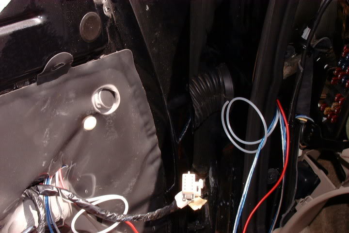
Next remove the left dash end panel (the one with the fuse door) by pulling it straight out. Be careful not to break the plastic tabs or slots that metal clips engage. You will also need to remove the door jamb trim near the hood release by removing the screws in the hood release lever and then pulling the trim out away from the door opening. Next remove the under dash trim panel by removing the 4 hex head screws. Your car should now look like this:

In order to get the vacuum line and
gauge light (and speaker wires in my case) from the
gauge to the firewall and beyond, I drilled a ½ inch hole to fit a 3/8 inch rubber grommet (be sure to use a grommet, sharp edges and wires/tubing don’t mix) through the door frame as pictured. Be very careful when drilling anywhere in these cars! They are crowded with wiring harnesses. Double check before drilling!

I removed the bellows that runs between the door and the body to check for wires first and also to make it easier to route my vacuum line and wires.
Using mechanics wire or a fish tape, pull the wire(s) and vacuum line through the 3/8 inch grommet, the door bellows and finally through an upper opening in the door shell that will be near the installed
gauge.

Now that the vacuum lines and wire(s) are routed, its time to mount the
gauge! Start by removing the HVAC vent and duct from the door panel by carefully removing the 2 push nuts that retain it. Carefully pull the vent panel from the duct, it is difficult but can be done w/o breaking the tabs. I chose to install the
gauge in the lower vent location to be sure I had enough clearance for the back side of the
gauge.
Remove the lower vent in the vent panel. I used a Dremel tool to remove the lip inside the boss that holds the vent. I removed only enough material to allow for the
gauge to fit very snug. Having a snug fit will help here since you can’t tighten the
gauge clamp too much w/o bending the vent panel. Position the
gauge however you want it in the vent panel. It may be helpful to test fit the vent w/
gauge in the door panel so that the
gauge is positioned how you want it. Next, install the
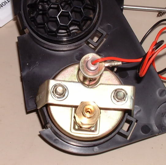
gauge clamp and two nuts, I had to spread my clamp a little to clear the boss. I also used a little blue Loctite on the
gauge nuts and studs since you can’t get them real tight w/o damaging the plastic parts.

Cut away the lower portion of the duct as shown. Seal the duct with a couple layers of duct tape (what else would you use?

). Reattach the vent assembly to the duct.

Reassemble the duct and vent assembly to the door panel. Connect the
gauge light power and ground wires to an appropriate source. I used the ashtray light for my 12V + power since I removed the ashtray to mount a CD changer remote display (another write-up). I found a suitable ground wire in one of the door panel wiring harnesses. Place the door panel bottom hooks into the door shell to support it while you connect the vacuum line. Be careful not to overtighten the fittings as you can crush the tubing. Then reconnect the factory wiring and reassemble door panel, door handle trim, and 5 screws. Reconnect the door bellows and you are done with the door. Time for a cold beer

.
Now we have to get the vacuum line out to the engine. I pulled back the carpet and insulation behind the pedals and drilled a ¼ inch hole through the firewall and installed a small grommet that the vacuum line passed through. Again, be careful not to hit a wiring harness or other component when drilling. I routed the vacuum line under the dash leaving a little slack here and there. I had to buy some extra vacuum line (the plastic kind) and a compression fitting to splice the lines under the dash in order to get to the engine. Secure with several zip ties.

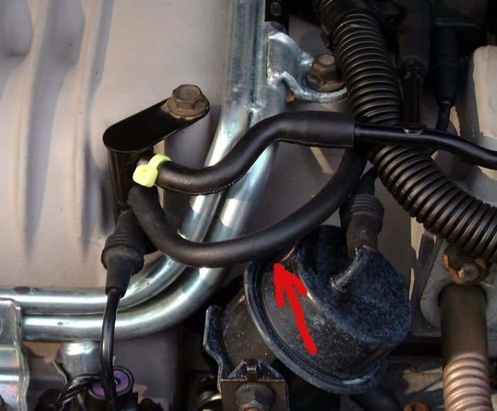
I purchased a brass ¼ NPT TEE, two 3/16 inch hose barbs, and a 1/8 inch hose compression fitting (for the
gauge vacuum line) from a local hardware store in order to make the connections to the engine as shown above. I removed the factory vacuum line that runs between the vacuum tree on the SC and the fuel pressure regulator and connected one line from the TEE to the vacuum tree using 3/16 inch rubber vacuum line (from NAPA) as shown (red arrow):

I then connected the fuel pressure regulator to the TEE, again with 3/16 inch rubber vacuum line. Last but not least I connected the vacuum line from the
gauge to the TEE using the 1/8 inch compression fitting. I then secured the Tee to a plastic bracket that is clipped to the engine’s plastic fuel lines using zip ties. I routed the
gauge vacuum line along the firewall using extra slots I found in my car’s factory steel fuel line guides near the brake booster. Be sure to leave a little slack here and there to allow the tube to move freely.
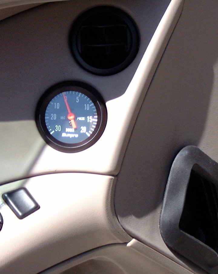
Now all that was left to do was to check the
gauge’s function and for leaks, reassemble the dash, and enjoy. Looks factory, doesn’t it? I just wish I could have disassembled my
gauge and painted the needle white like my stock gauges. Time start to finish was about 4 hours including breaks.


