| | FGT supercharger swap project |  |
|
+12jbird AA deekster_caddy Abaddon damnjetski Karma Jack the R KnottyEagle stan charlieRobinson matt270avian turtleman 16 posters |
|
| Author | Message |
|---|
turtleman
Expert

Name : Codith
Age : 37
Location : Villa Park, IL
Joined : 2007-02-08
Post Count : 3671
Merit : 140
 |  Subject: Re: FGT supercharger swap project Subject: Re: FGT supercharger swap project  Thu Jul 09, 2015 1:46 am Thu Jul 09, 2015 1:46 am | |
| - charlieRobinson wrote:
- turtleman wrote:
- matt270avian wrote:
- Well it's been almost a month.... Where did you come from where did you go?
Doing my motor - see tortuga thread
Incidentally I'll be back to an L67 bottom end so it'll be begging for an oversized blower now.
why no more L26? It's just a matter of what was available and convenient to get for a replacement engine | |
|
  | |
turtleman
Expert

Name : Codith
Age : 37
Location : Villa Park, IL
Joined : 2007-02-08
Post Count : 3671
Merit : 140
 |  Subject: Re: FGT supercharger swap project Subject: Re: FGT supercharger swap project  Wed Aug 05, 2015 1:37 am Wed Aug 05, 2015 1:37 am | |
| 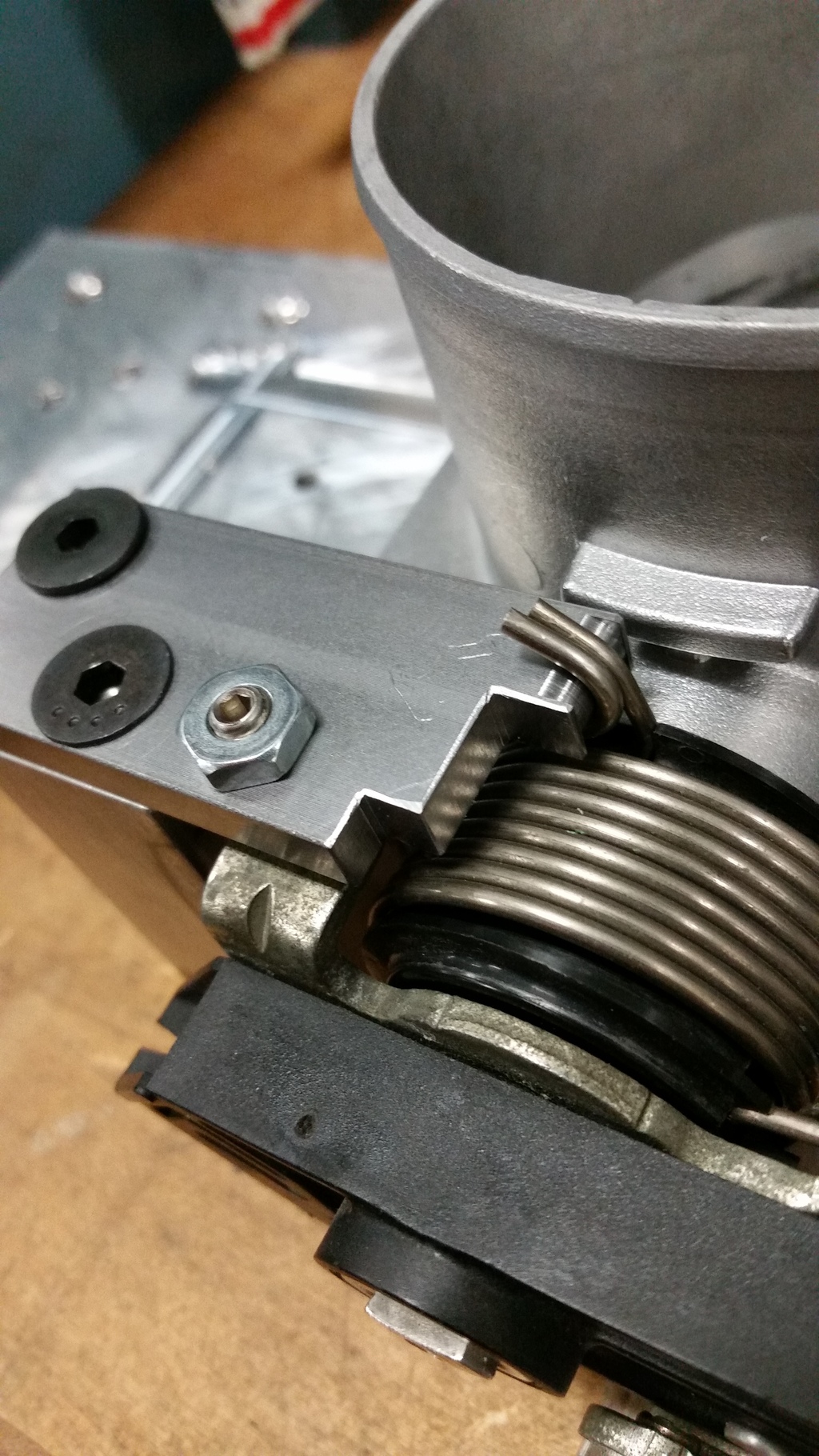 pretty much got the leg made up for the return springs, idle adjustment screw, and wot stop 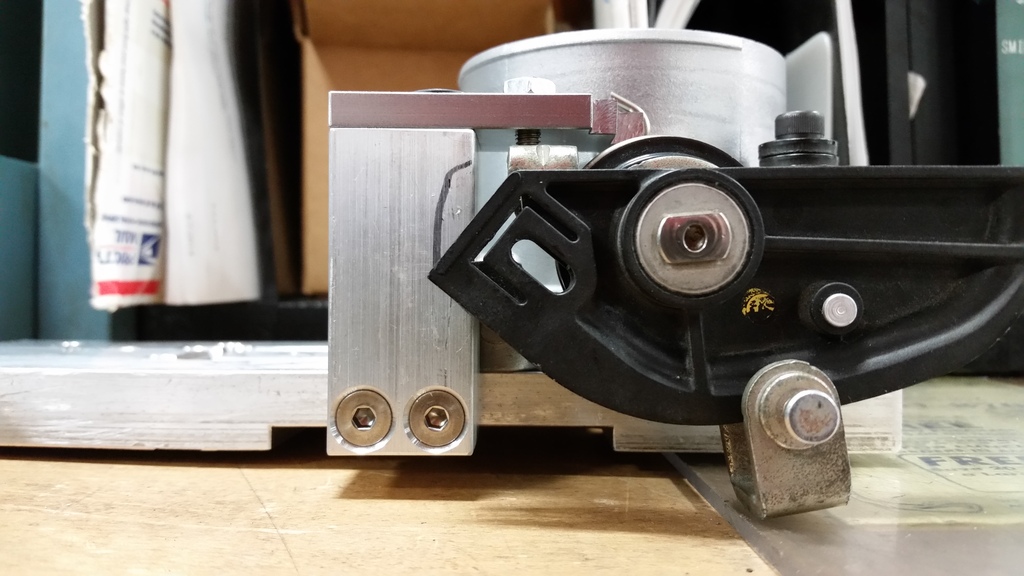 wasn't done but good shot of how that all works  Everything landed how I overall planned it to. The converted throttle body got more hacking to get unneeded material off and make it look a little nicer. The L32 throttle body that is not getting raped just gets the coolant passage removed and that's about it. They become siamese to the greatest extent spacially possible and incidentally fall within about .010" of the blower's opening width. 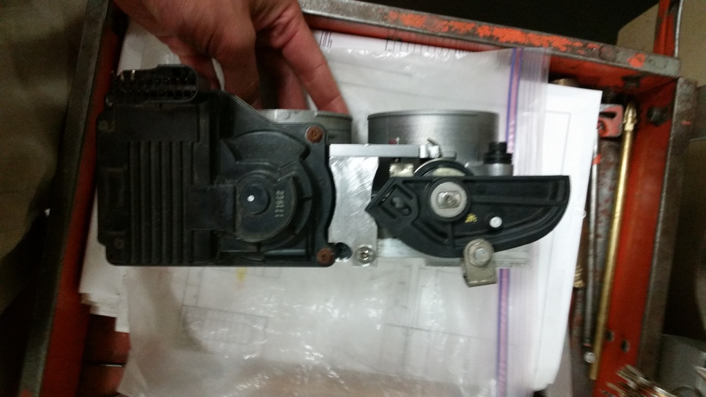 side (actually bottom once it's on) view. I ended up needing a bunch of little clearance here - little clearance there shit on the stand to clear the throttle bodies 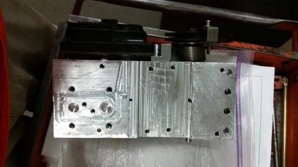 bottom  top Other thing is the throttle cable bracket which I started working on a little bit today. I pretty much copied the zzp one for the northstar and I just need to mount it in the same fashion as the other stand with the 8 degree angle and all It's probably gonna be easiest and awesomest just to run two discrete 3" intakes with dual combined mafs and two air filters. The primary throttle body takes air in through a longer tube from the fender like factory and the secondary just gets air right through the hood via a scoop. just kidding! I'm kidding right? Or am i? I don't know | |
|
  | |
charlieRobinson
Expert

Name : Charlie
Age : 39
Location : Knoxville, TN
Joined : 2011-05-17
Post Count : 3924
Merit : 31
 |  Subject: Re: FGT supercharger swap project Subject: Re: FGT supercharger swap project  Wed Aug 05, 2015 8:50 pm Wed Aug 05, 2015 8:50 pm | |
| I would put both filters in the path of the hood scoop.
I think a scoop that just flows air right on top of the blower would make gains happen. | |
|
  | |
matt270avian
Expert

Name : Matt
Age : 28
Location : Frederick, MD
Joined : 2012-01-15
Post Count : 2681
Merit : 54
 |  Subject: Re: FGT supercharger swap project Subject: Re: FGT supercharger swap project  Wed Aug 05, 2015 8:58 pm Wed Aug 05, 2015 8:58 pm | |
| How are you going to merge them into one intake though? Make a plate of aluminum that goes around both of them and tapers down into a 4-5" tube? | |
|
  | |
turtleman
Expert

Name : Codith
Age : 37
Location : Villa Park, IL
Joined : 2007-02-08
Post Count : 3671
Merit : 140
 |  Subject: Re: FGT supercharger swap project Subject: Re: FGT supercharger swap project  Fri Aug 07, 2015 1:03 pm Fri Aug 07, 2015 1:03 pm | |
| You know what I'm not sure yet. I've got some ideas but nothing really solid at this point. I know I'm gonna want to have a compound angle for the throttle bodies going forward and down to the fenderwell to avoid clearance problems with the coolant tank area and the hood. It seems like the easiest way to do that would be make a low profile plate to mount to the blower and give me the 3" flanges to have two angled tubes come out and go into another flange that the throttle bodies mount on. That avoids making me fabricate a really complicated piece but might look kinda weird. Then maybe make a Y out of billet aluminum that would incorporate the maf sensor. That part would be doable aside from making a nice transition inside. | |
|
  | |
matt270avian
Expert

Name : Matt
Age : 28
Location : Frederick, MD
Joined : 2012-01-15
Post Count : 2681
Merit : 54
 |  Subject: Re: FGT supercharger swap project Subject: Re: FGT supercharger swap project  Sun Feb 21, 2016 6:38 pm Sun Feb 21, 2016 6:38 pm | |
| | |
|
  | |
charlieRobinson
Expert

Name : Charlie
Age : 39
Location : Knoxville, TN
Joined : 2011-05-17
Post Count : 3924
Merit : 31
 |  Subject: Re: FGT supercharger swap project Subject: Re: FGT supercharger swap project  Sun Feb 21, 2016 11:26 pm Sun Feb 21, 2016 11:26 pm | |
| yeah, man. we need a status update. | |
|
  | |
turtleman
Expert

Name : Codith
Age : 37
Location : Villa Park, IL
Joined : 2007-02-08
Post Count : 3671
Merit : 140
 |  Subject: Re: FGT supercharger swap project Subject: Re: FGT supercharger swap project  Wed Feb 24, 2016 2:55 am Wed Feb 24, 2016 2:55 am | |
| I don't want to tease - there's hasn't been any notable progress that last few months.
I'm waiting to register for a couple drafting/autocad classes in the summer at my community college so that I can make the full model of the adapter plate / IC to then CNC machine out. I'm not even joking. There is some goofy loft machine work that will need to be done for the top for it to transition nicely. I have the blower and lower intake bolt pattern and critical openings all mapped out in 2D and james got at least one WBS intercooler plate done as well which means I have all the information to build on but I need to construct a good 3D model to export to my CAM software at work which can then facilitate the actual machining process - the CAM software takes my model and generates all of the 3-axis machine moves to make it. Being a machinist, I simply cannot make this something that looks like it could have been done in a shed with lawn tools, not to mention the intercooler and bypass need to be at least as good as current if not better. Bigger blower needs a bigger bypass circuit so the half-blocked 1.5" section that the typical intercooler gives you isn't cutting it for me.
Another hurdle (although it can be postponed) is figuring out how the double throttle body is all gonna work. That's going to be a project in its-self but I do feel it's crucial to getting the potential out of this blower. I'm starting to investigate the possibility of getting the throttle body angle plenum 3d printed - again after I learn how to model it properly. It's possible this will also have two completely separate intakes including twin maf sensors by the time I'm done.
I managed to finish the double throttle body plate and all those bits so i'll post pics of that soon | |
|
  | |
Karma
Aficionado

Name : Andrew
Age : 40
Location : Ontario, Canada
Joined : 2008-01-14
Post Count : 1949
Merit : 123
 |  Subject: Re: FGT supercharger swap project Subject: Re: FGT supercharger swap project  Wed Feb 24, 2016 9:10 am Wed Feb 24, 2016 9:10 am | |
| "Being a machinist, I simply cannot make this something that looks like it could have been done in a shed with lawn tools"
Wow! You have managed to distill into a single sentence what has taken me ages to get some people to understand! _________________  | |
|
  | |
Abaddon
Expert

Name : Scott
Location : Macomb, Michigan
Joined : 2010-02-24
Post Count : 4316
Merit : 185
 |  Subject: Re: FGT supercharger swap project Subject: Re: FGT supercharger swap project  Wed Feb 24, 2016 10:36 am Wed Feb 24, 2016 10:36 am | |
| - Karma wrote:
- "Being a machinist, I simply cannot make this something that looks like it could have been done in a shed with lawn tools"
Wow! You have managed to distill into a single sentence what has taken me ages to get some people to understand! You don't like "Billy Bobs Backyard Mechanics and Mammoplasty" ????  | |
|
  | |
charlieRobinson
Expert

Name : Charlie
Age : 39
Location : Knoxville, TN
Joined : 2011-05-17
Post Count : 3924
Merit : 31
 |  Subject: Re: FGT supercharger swap project Subject: Re: FGT supercharger swap project  Wed Feb 24, 2016 11:07 am Wed Feb 24, 2016 11:07 am | |
| could the 2nd throttle body be hard linked to the 1st? So only 1 cable is needed on 1 throttle body? | |
|
  | |
turtleman
Expert

Name : Codith
Age : 37
Location : Villa Park, IL
Joined : 2007-02-08
Post Count : 3671
Merit : 140
 |  Subject: Re: FGT supercharger swap project Subject: Re: FGT supercharger swap project  Wed Feb 24, 2016 2:04 pm Wed Feb 24, 2016 2:04 pm | |
| - Abaddon wrote:
- Karma wrote:
- "Being a machinist, I simply cannot make this something that looks like it could have been done in a shed with lawn tools"
Wow! You have managed to distill into a single sentence what has taken me ages to get some people to understand!
You don't like "Billy Bobs Backyard Mechanics and Mammoplasty" ????  Haha there's another gentleman, Zeph, on TCG that I talk to (pretty much pioneered the multiple ICM thing) that is doing similar bizarre projects and he is the complete opposite. It's almost as if he makes it look hacked on purpose. I could do that if it was a junky car I didn't really care about but not a riv. In the end I'd rather be slow and in a riv  haha | |
|
  | |
turtleman
Expert

Name : Codith
Age : 37
Location : Villa Park, IL
Joined : 2007-02-08
Post Count : 3671
Merit : 140
 |  Subject: Re: FGT supercharger swap project Subject: Re: FGT supercharger swap project  Wed Feb 24, 2016 2:06 pm Wed Feb 24, 2016 2:06 pm | |
| - charlieRobinson wrote:
- could the 2nd throttle body be hard linked to the 1st? So only 1 cable is needed on 1 throttle body?
That part of it is actually pretty much sorted out. The second throttle body is electronic (L26/32/etc) so no cable necessary. It's going to kinda act like the secondary butterflys on a carburetor  | |
|
  | |
turtleman
Expert

Name : Codith
Age : 37
Location : Villa Park, IL
Joined : 2007-02-08
Post Count : 3671
Merit : 140
 |  Subject: Re: FGT supercharger swap project Subject: Re: FGT supercharger swap project  Sun Mar 13, 2016 10:59 pm Sun Mar 13, 2016 10:59 pm | |
| some tidbits 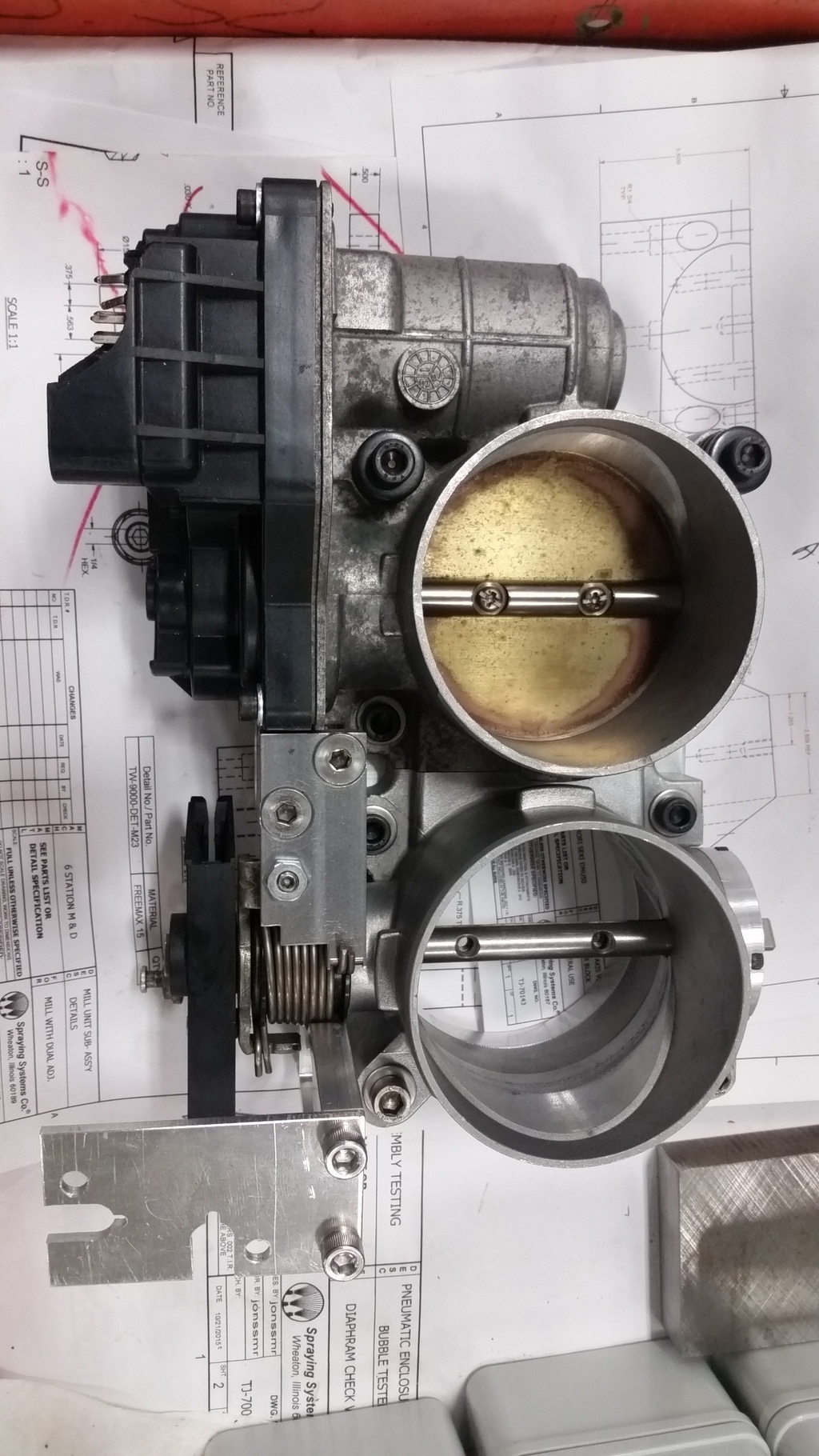 I have an actual plate made now for the double tb's - not just a scrap test piece - everything fits tight & neat It took a bit of trial and finesse to make things fit together. 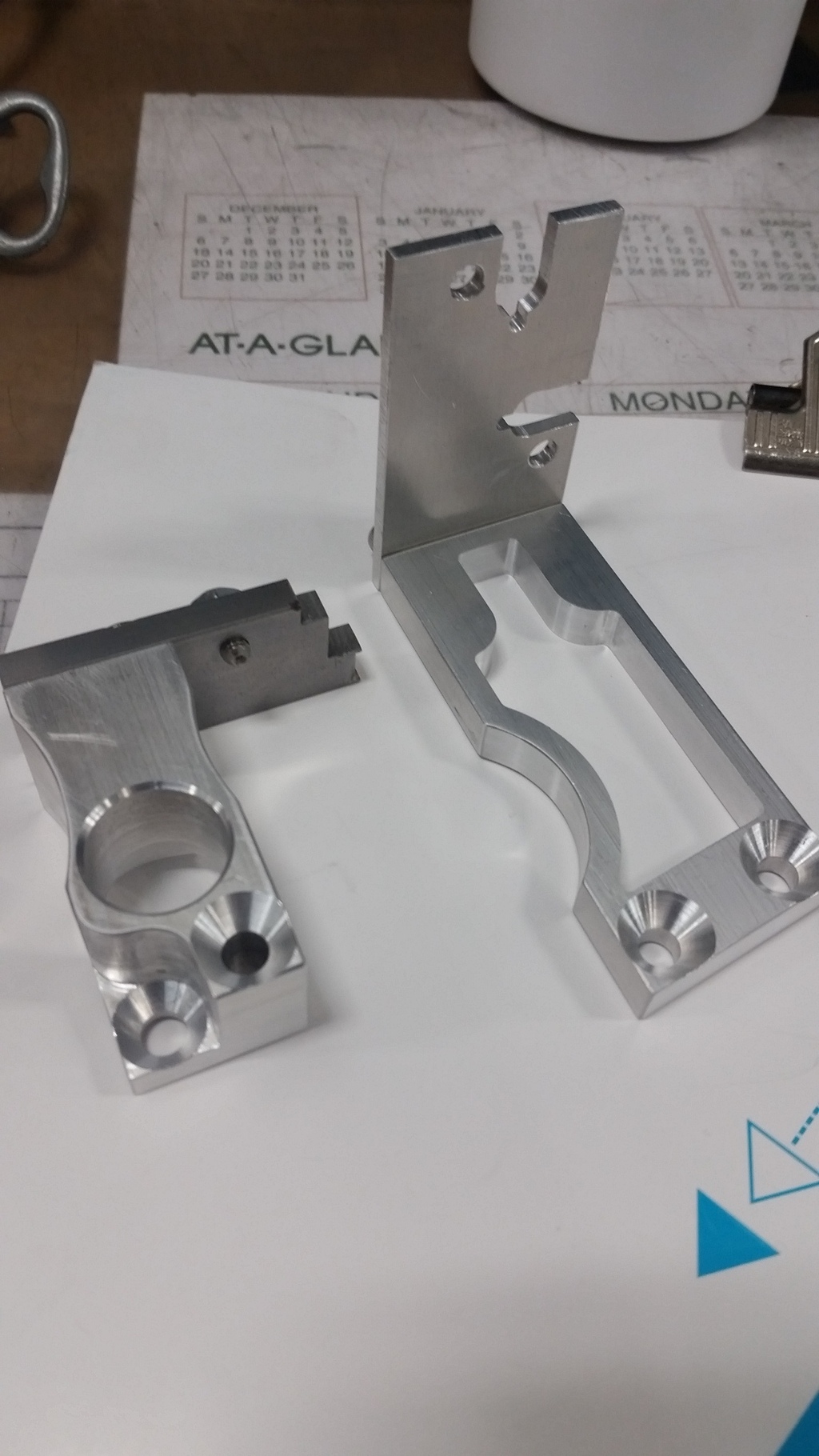 cable bracket and bracket for return spring and whatnot I gotta find a pic of it later but I also made a little spring reversal insert that fits into the electric throttle body's gearbox. Like a mechanical, it has double springs fit in place with a plastic ring piece right on the pivot shaft. The way they designed this electric one though, one of the two springs actually pinches the throttle blade partially open when de-energized (I reckon to provide a total failure limp home state) and since I wasn't planning to use the whole built-in controller and was just going to be modulating full-duty power when I want it open, I needed to undo that and make it close all the way at rest. My insert basically just braces the reversed spring in such a way where it's spring the opposite direction and just helping keep the butterfly closed by re-positioning the spring end perches. Still trying to decided how to hang that on the blower. I still feel like it needs to come right out at a forward & downward angle in order to get piping going the right way and clear everything. I think If I try to go straight up to the blower and then make turns with the intakes leading up to the tb's, I'm going to have problems. Once that is figured out, the rest should be fun. Right now I'm thinking totally independent intakes with twin 85mm mafs is actually easiest and really good since that'll flow like crazy. Something singular would be very tough to make flow well enough - it'd have to be huge and funny dimensions, the maf would have to be huge which I don't really like - hard to get a nice calibration with. Although I haven't found much on the matter of twin mafs, I feel it should be doable with a frequency mixer circuit. I'm not genius enough to foresee exactly how the two mafs' curves with work out in real life so i'm just gonna have to try. | |
|
  | |
deekster_caddy
Master
Name : Derek
Age : 52
Location : Reading, MA
Joined : 2007-01-31
Post Count : 7717
Merit : 109
 |  Subject: Re: FGT supercharger swap project Subject: Re: FGT supercharger swap project  Mon Apr 11, 2016 9:33 pm Mon Apr 11, 2016 9:33 pm | |
| So I haven't been on in a while... just read this whole thread. The one question I don't see brought up (maybe I missed it?) is about the bypass opening. How do you get those back to each other? A diagonal bore in a large IC as an adapter plate?
Otherwise it's looking awesome, and like a lot of fun! | |
|
  | |
turtleman
Expert

Name : Codith
Age : 37
Location : Villa Park, IL
Joined : 2007-02-08
Post Count : 3671
Merit : 140
 |  Subject: Re: FGT supercharger swap project Subject: Re: FGT supercharger swap project  Tue Apr 12, 2016 12:51 am Tue Apr 12, 2016 12:51 am | |
| - deekster_caddy wrote:
- So I haven't been on in a while... just read this whole thread. The one question I don't see brought up (maybe I missed it?) is about the bypass opening. How do you get those back to each other? A diagonal bore in a large IC as an adapter plate?
I wish I could model it right now to show it but I haven't learned 3D yet. I'm starting courses in June actually. But anyway I have a whole plan for the bypass. If I stick with my idea of using the Ed Labarge style intercooler with three layers, I'm going to mill a huge channel through to connect the bypass ports of the LIM and blower (which means I need a fair amount of extra material on the throttle body side of the intercooler (I've already cleared this with Ed so that shouldn't be a problem). I'm actually going to be widening the bypass channel in the LIM its-self in order to get more section area for flow since This bigger blower makes bypass more critical and the IC does kinda interrupt that as is. So when you are looking down at the LIM, there will be the big opening for the IC and instead of a half a circle for the stock bypass, it'll be a slanted rectangle (slanted because the IC core sits at an angle in Ed's IC). The M90 has a 1.5" bypass valve - the FGT blower has a 1.75". I'm hoping to maintain close to that section area but certainly I need to do better than the standard IC's where half the opening is just covered up lol. | |
|
  | |
deekster_caddy
Master
Name : Derek
Age : 52
Location : Reading, MA
Joined : 2007-01-31
Post Count : 7717
Merit : 109
 |  Subject: Re: FGT supercharger swap project Subject: Re: FGT supercharger swap project  Thu Apr 14, 2016 7:20 pm Thu Apr 14, 2016 7:20 pm | |
| Got it. Just curious. Inquiring minds you know...
So basically you are going to make a custom IC that bolts to the 3800 LIM on the bottom and receives the FGT SC on the top, with a few ports moving wide inside the IC surround. You could also use that to line up the pulley if it didn't line up exactly the way you like.
Another thought - you could actually mill the whole top surface at an angle bringing the drivers side lower if you needed to give the throttle body a little more hood clearance. I don't think there's anything that requires it being level. The IC fins will straighten out any potential airflow issues. | |
|
  | |
turtleman
Expert

Name : Codith
Age : 37
Location : Villa Park, IL
Joined : 2007-02-08
Post Count : 3671
Merit : 140
 |  Subject: Re: FGT supercharger swap project Subject: Re: FGT supercharger swap project  Tue Apr 19, 2016 3:12 pm Tue Apr 19, 2016 3:12 pm | |
| - deekster_caddy wrote:
- So basically you are going to make a custom IC that bolts to the 3800 LIM on the bottom and receives the FGT SC on the top, with a few ports moving wide inside the IC surround. You could also use that to line up the pulley if it didn't line up exactly the way you like.
yup! and yes, one of the things I am doing with the mock-up motor on the stand right now is trying to get the pulley alignment perfect and then plot out my final position from that. The FGT blower as is has a snout length almost exactly like the m90 so it's just a matter of tweaking. James is trying to get me to move the blower towards the driver side of the car and extending the snout via an adapter which I could do pretty easily. The point being to get the discharge of the blower towards the back of the engine to try to reduce the forward flowing problem where the air coming out of the blower all wants to go over to cyl 1 & 2 so they have a lean tendency under high flow conditions. I think the intercooler has to help a lot with that but I'm not gonna worry about it. Doing something like that would make everything much harder. For height, I know the blower is fine with a 2.5" thick IC under it. If I hold to my original plan, it'll actually be 2.375" tall but the throttle body end of things is gonna be an issue either way. Right now that's actually my biggest obstacle because I can't make that turndown myself. It needs to be fabricated or cast/printed. The idea of tilting the blower isn't gonna be enough for the angle I need without messing up the belt drive. | |
|
  | |
turtleman
Expert

Name : Codith
Age : 37
Location : Villa Park, IL
Joined : 2007-02-08
Post Count : 3671
Merit : 140
 |  Subject: Re: FGT supercharger swap project Subject: Re: FGT supercharger swap project  Mon Oct 24, 2016 7:35 am Mon Oct 24, 2016 7:35 am | |
| So I got some motivation and threw the needed parts on the mockup motor to get the belt alignment double checked and started sketching. Thanks to James I had mappings for a gen3 m90, my fgt blower, and a wbs ic which all helped me to make a good drawing after a lot of fussing around trying to get these drawings lined up and whatnot. I purchased material. 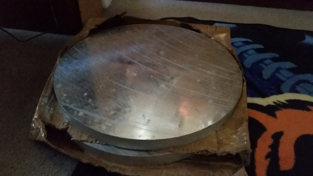 $240 worth of aluminum - these are two 1.25" thick roughly 18" diameter plates of precision cast (aka mic-6) 6061 - very nice flat, sound material I priced out an intercooler cartridge from BIC. Their online custom core ordering catalog is very good. I could make one of the usual mazda millennia heater cores that are used in the zzp & wbs IC's work too but I wanted something more robust (bar & plate) for the extra stress it'll be put through with this supercharger. The constant pressure changes does cause some deflection in the core tubes and is a worthy failure concern particularly with more boost.  That's my quick blueprint to send to BIC. I'm guessing based off of vendor testimonys that this isn't going to be better than the typical heater core used in terms of charge cooling under normal (m90) conditions but I'll be able to handle more extremes. It's slightly wider and thicker (about the same length) and as you can tell by the blueprint, it'll be single pass. Some of my drawings 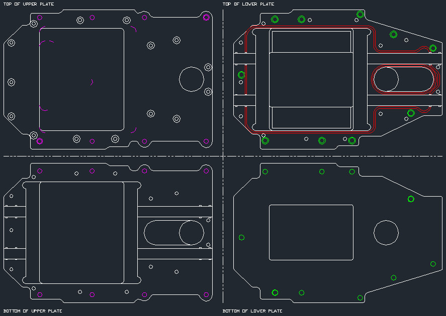 These are mainly what I'll be using to make the plates - they represent pretty much exactly what each side looks like. Theres nothing too wild going on but the reason the top of the lower plate looks so busy is that surface will have the channels machined for a viton o-ring to seal the plates to eachother. O-rings will also seal up around the coolant tubes and kind of suspend the core in the case somewhat. I could have just sealed this up with rtv just like zzp/wbs does but that would kind of suck because since my cooler is an adapter as well with two discrete bolt patterns that conflict in a couple spots I have to isolate them to their respective layers if that makes any sense and as a result, I have to install/uninstall the core layer by layer which means having it glued together with rtv would be really inconvenient if I have to take it back off the motor. This way I only need to dap a little tiny bit of rtv in the spots where there's breaks in the orings.  The bolt patterns and stuff laid together     I just roughly sketched the profiles in solidworks just to make sure my mental picture matches reality haha | |
|
  | |
turtleman
Expert

Name : Codith
Age : 37
Location : Villa Park, IL
Joined : 2007-02-08
Post Count : 3671
Merit : 140
 |  Subject: Re: FGT supercharger swap project Subject: Re: FGT supercharger swap project  Sat Nov 12, 2016 1:49 pm Sat Nov 12, 2016 1:49 pm | |
| Updates:
I changed the plan a little - I'm going with a bigger core now - same 6" long (not including end tanks) by 7.3" wide but instead of the 2.25" thick I'm going with a 4.5" thick. It's a monster by comparison. Since I already purchased the two 2.25" plates, I'm just adding one more 2.5" thick plate in the middle of the sandwich to make up the difference with change. The assembly will be 5" thick now which means fitting it under the hood is out of the question. I'm gonna need to make a cowl or something. I'll worry about that later - one thing at a time. I believe the bigger cooler is gonna be necessary though. I was talking to jdredd who currently owns the nice whipple gp about heat and that blower pours out heat like an oven. He's got a 6x6x3 bar&plate core in there and he would probably benefit greatly from more. I'm gunning for the title here I guess. If you're going excess, go excess right?
The core itsself should be getting made now - it didn't really affect the cost appreciably making it twice as thick (just bigger extrusion stock) - half the cost is all the labor making a setup and welding the end tanks with the pipes to my specification.
I think I'll be pretty ok on cooling so the big issue will be trying to get the serpentine belt to drive this thing into 20-30psi. No known factory tensioner + belt wrap arrangement is enough as jdredd is experiencing. Cog drive unfortunately just had nothing but problems for them (prj/jonbob/jdredd) so they kinda tossed the idea and went back to serpentine now. I have one possible idea floating around in my head that i'll try. I'm gonna add a lever/linkage to the tensioner arm and fasten a two-way pneumatic actuator to it that gets fed boost. In premise it won't do anything until I get into boost and then it'll add extra tension to the belt. The theory of it sounds promising. The challenge will be making it fit and whatnot and also keeping the dampening affect the actuator will impose from hurting the tensioner's normal action. | |
|
  | |
turtleman
Expert

Name : Codith
Age : 37
Location : Villa Park, IL
Joined : 2007-02-08
Post Count : 3671
Merit : 140
 |  Subject: Re: FGT supercharger swap project Subject: Re: FGT supercharger swap project  Fri Feb 24, 2017 2:06 pm Fri Feb 24, 2017 2:06 pm | |
|  time for some proof this is still going down - I'm getting some momentum again This is all really difficult to explain I'm finding. The guys at work are asking me about this since it's sitting out on a machine most of the time now and I try to lay it down but it doesn't make much sense (even to seasoned tool makers) You pretty much have to already know all about oem supercharger arrangements and water intercoolers and stuff. So if this seems like technical hieroglyphics, hang in there, it'll make some more sense when more of its done and you get to see all the bits go together.  the top of the top (out of 3) plate is done. still lots of work on the bottom of it yet   Here's the nearly $200 2.5" thick billet i'm cutting most of the material out of and throwing away that is the middle plate lol 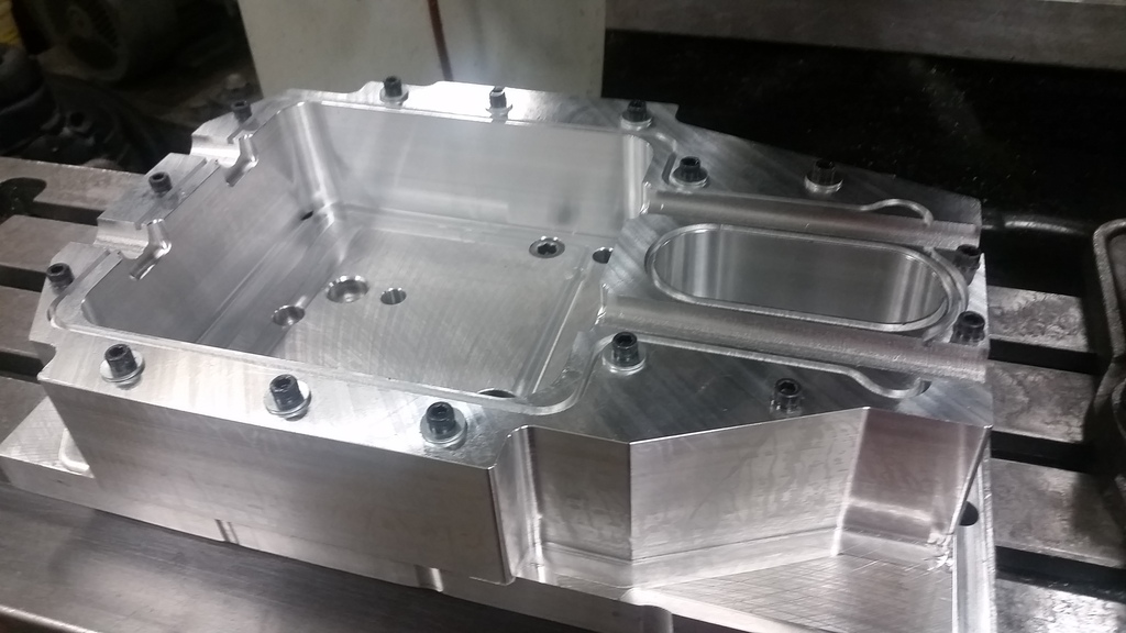 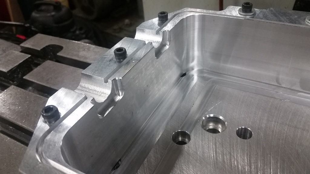 very nearly finished I still need to do the bottom of the top plate and also get going on the bottom plate which I haven't even gotten the material for yet (because my plans changed a little and I need thicker material than i originally got. There's a lot to do but it's progressing pretty well. I put in lots of off-clock hours for stuff that I really need to babysit the machine for. For operations that I can pretty much set up and walk away for a while I can do on the clock so it's not terribly bad.
Last edited by turtleman on Mon Feb 27, 2017 2:01 pm; edited 1 time in total | |
|
  | |
AA
Administrator

Name : Aaron
Age : 47
Location : C-bus, Ohio
Joined : 2007-01-13
Post Count : 18452
Merit : 252
 |  Subject: Re: FGT supercharger swap project Subject: Re: FGT supercharger swap project  Fri Feb 24, 2017 3:55 pm Fri Feb 24, 2017 3:55 pm | |
| Nice work! It's easy to see why CNC parts are so expensive. People sometimes complain about the cost of billet alum valve covers and caps, but look at how they're made. Hope you can recycle the swarf at least. _________________ '05 GTO 6.0L • 6-spd • 95k miles • 0-60: 4.8s • 16.9 avg MPG • Nelson Ledges Lap: 1:26'95 Celica GT 2.2L • 5-spd • 165k miles • 0-60: yes'98 SC Riviera • 281k miles • 298 HP/370 TQ • 0-60: 5.79s • ET: 13.97 @ 99.28 • 4087 lb • 20.1 avg MPG • Nelson Ledges Lap: 1:30
3.4" pulley • AL104 plugs • 180º t-stat • FWI w/K&N • 1.9:1 rockers • OR pushrods • LS6 valve springs • SLP headers • ZZP fuel rails
KYB GR2 struts • MaxAir shocks • Addco sway bars • UMI bushings • GM STB • Enkei 18" EV5s w/ Dunlop DZ101s • F-body calipers
EBC bluestuff/Hawk HP plus • SS lines • Brembo slotted discs • DHP tuned • Aeroforce • Hidden Hitch^^^ SOLD ^^^  '70 Ninety-Eight Holiday Coupe 455cid • 116k miles '70 Ninety-Eight Holiday Coupe 455cid • 116k miles^^^ SOLD ^^^  | |
|
  | |
Abaddon
Expert

Name : Scott
Location : Macomb, Michigan
Joined : 2010-02-24
Post Count : 4316
Merit : 185
 |  Subject: Re: FGT supercharger swap project Subject: Re: FGT supercharger swap project  Sun Feb 26, 2017 7:42 pm Sun Feb 26, 2017 7:42 pm | |
| Dang, Cody. You gonna CNC some wings too? You're a sick man  | |
|
  | |
turtleman
Expert

Name : Codith
Age : 37
Location : Villa Park, IL
Joined : 2007-02-08
Post Count : 3671
Merit : 140
 |  Subject: Re: FGT supercharger swap project Subject: Re: FGT supercharger swap project  Mon Feb 27, 2017 2:21 pm Mon Feb 27, 2017 2:21 pm | |
| I forgot to post the intercooler cartridge itself from BIC.  hashtag girth   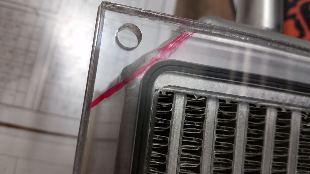 here i made a quick template to make sure my o-ring dimensions were good The struggle was coming up with a way to positively seal around the intercooler core. This isn't necessarily critical (none of the vendors do that) but the the core itsself not being square all around and having the weld seams and stuff i'm gonna end up with some needed clearances around it and therefore gaps that the air charge would sneak through. I didn't want that so I'm o-ringing the core on both sides. I gotta be very good with the dimensions to pull that off. | |
|
  | |
turtleman
Expert

Name : Codith
Age : 37
Location : Villa Park, IL
Joined : 2007-02-08
Post Count : 3671
Merit : 140
 |  Subject: Re: FGT supercharger swap project Subject: Re: FGT supercharger swap project  Tue Sep 18, 2018 7:09 pm Tue Sep 18, 2018 7:09 pm | |
| I have a lot of catching up on updates to do but as of now the FGT blower is on and works. I've been posting stuff about it here & there on social media out of convenience. It takes some steps to do it here but I'll get more gooey info on it soon hopefully. I still have lots to do  *fixed the tiny pic
Last edited by turtleman on Wed Sep 19, 2018 10:53 am; edited 2 times in total | |
|
  | |
Sponsored content
 |  Subject: Re: FGT supercharger swap project Subject: Re: FGT supercharger swap project  | |
| |
|
  | |
| | FGT supercharger swap project |  |
|


